Regardless of the measuring principle (mass flow, differential pressure) of the pneumatic module, one and the same electronic module (Plug-and-Play) can be used for replacement in the event of service. The electronic module detects the connected measurement technology and activates the appropriate software.
Expanded possibilities for IT and measurement technology
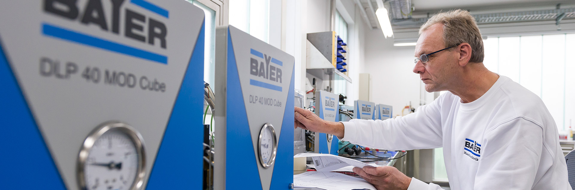
Modern and sturdy equipment technology is the basis of any leak test. We have just successfully launched the fourth generation of leak test instruments onto the market and are constantly developing them further.
The DLP 40 technology is a step forward in the development of BAYER leak testing technology. It integrates innovative measurement technology with modern PC information technology.
In addition to various electronic interfaces (e.g., Ethernet, Profinet, USB, etc.) for data transmission, DLP 40 offers extended options for statistical evaluation (database with filter functions, qs-STAT® interface) or the operation of higher-level, standardised interfaces such as XML.
DLP 40 is available in a conventional device design or, if requested by the customer, in a modular design; the components used are identical.
Q-DAS® certified data export interface for AQDEF
- Software:Windows 10 operating system, Measuring and visualisation software (DLP 40 MOD Control, Database software (DLP 40 MOD DB), Graphical user interface for intuitive operation, Self-explanatory operating symbols, Integrated interface to qs-STAT®, Help texts for parameters and online documentation
- Hardware design:Modular design by separation into pneumatic and electronic modules, Hardware change by Plug and Play: One electronic module for all measuring principles, one PC for visualisation and operation with 12.1" touch panel. The DLP 40 leak testing concept provides both a compact single instrument solution and a modular solution (separation of operation and measurement technology).
- Measurement principles:Mass flow, Pressure drop/pressure rise. Volume flow, Back pressure, Pressure rise
- Interfaces:1x PROFIBUS and/or 1x PROFINET and/or 1x Ethernet for control, 1x parallel interface to the PLC with 16 digital inputs and outputs each, 1x RS 232
- Interfaces:Visualisation PC (DLP 40 MOD PC): 2x Ethernet, 2x USB interface on front panel
- Resolution:0.1 Pa at differential pressure, 0.01 cm³/min at mass flow
- Pressure ranges:Vacuum, 1 bar, 4 bar, 10 bar, 16 bar
- Voltage supply:24 V DC
- Protection class:IP 54
- Options:Temperature compensation, Read-in of a barcode
Dialogue Leak Processor DLP 40
The modular solution allows a spatial separation of measurement technology (in the form of the measurement module) and visualisation. The option of modularising the DLP 40 leak test technology offers the following advantages and possibilities:
- Layout flexibility when integrating a module and its input PC due to spatial separation
- Close proximity of the modules to the leak test location
- Equal environmental conditions as for the workpieces
- Short hose lengths enabling faster filling and more accurate measurement
- Combining varied measuring methods (differential pressure, mass flow, etc.)
- Cost saving: one central visualisation PC for up to 4 measuring modules
Dialogue Leak Processor DLP 40
With the DLP 40, BAYER offers a combination of modern PC information technology and innovative measurement technology.
In addition to the graphic visualisation of the measuring process and an online documentation (operating instructions), it is possible to evaluate the integrated database with the help of filter functions according to various criteria (workpiece number, programme, date, etc.).
Statistical tools such as bar charts, histograms and quality control charts round off the offer.
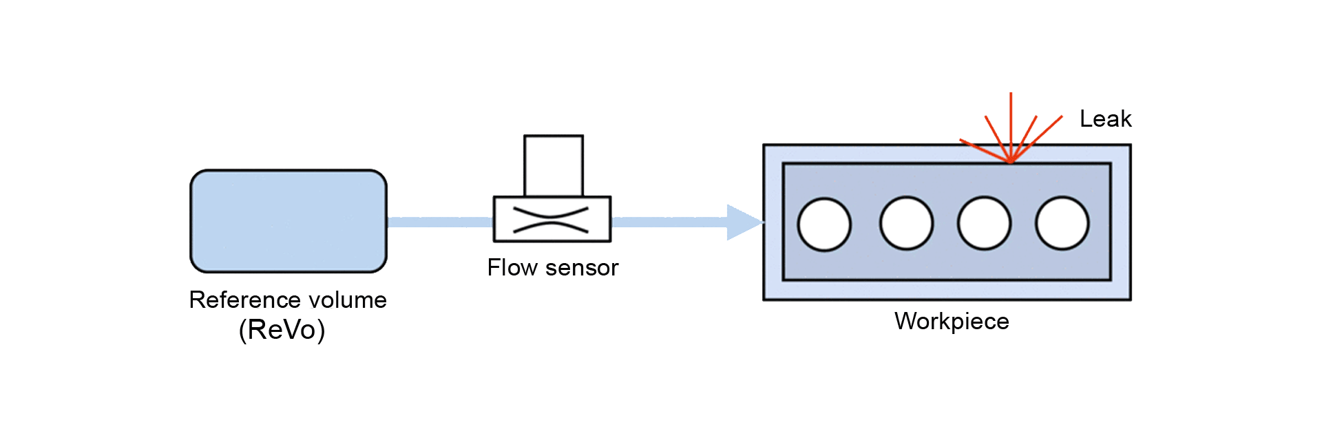
The mass flow method fills the part to be tested from a prefilled reference volume (ReVo). After a balancing phase, the balance flow caused by a possible leak between the connected volumes is determined at the end of the measurement time.
With the differential pressure process, either the pressure drop or the pressure rise can be measured. The part to be tested is filled with compressed air or it is evacuated. At the end of the filling process, the test chamber is separated from the filling unit and the pressure change in the sample that occurs during the measurement time is measured. If the part to be tested is leaking, the pressure will decrease over time in the sample. In the case of vacuum tests, the leaking part is detected by a pressure in the sample that increases with time.

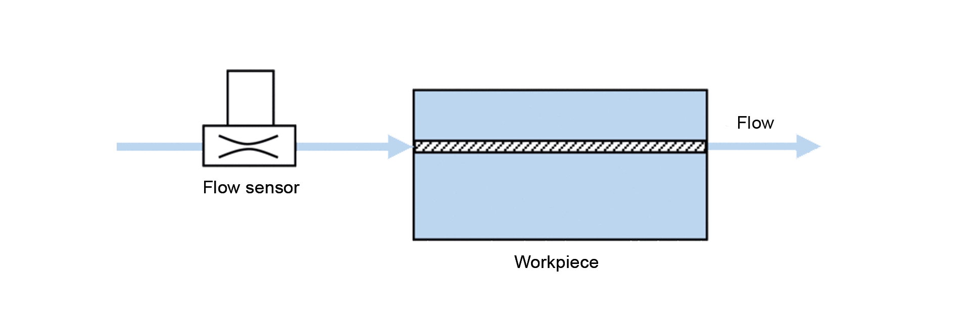
If workpieces are to be tested for a defined flow rate, the volume flow rate is used. Typically, the flow rate method is used for tubing, pipes (fuel pipes) and valves (e.g., ball seat valves); the flow rates are usually relatively high.
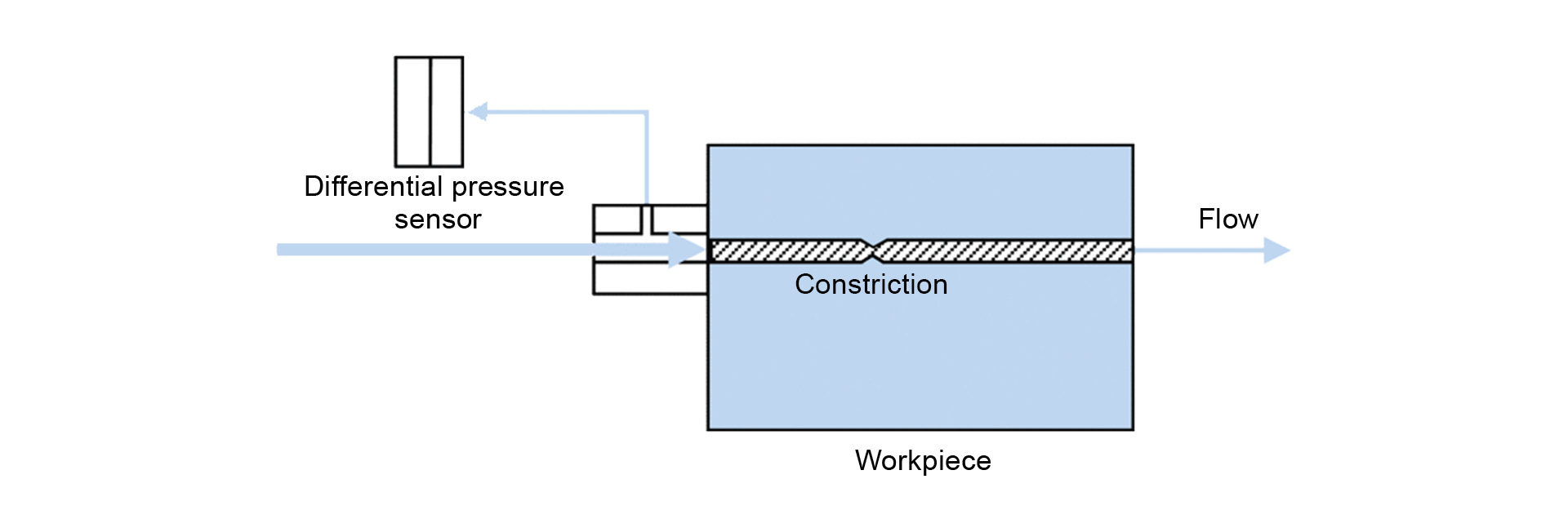
Here, the back pressure is measured on workpieces. By means of this measurement, you can check whether a borehole has been drilled with the correct diameter or whether a channel in a casting that cannot be seen optically has a constriction.
The workpiece to be tested is filled with compressed air by another leak test module (differential pressure or mass flow) and a measurement is carried out from the inside to the outside. After the measurement, the workpiece remains filled and is not vented (measurement 1). The pressure rise module then fills the surrounding space to a higher pressure. A possible leakage is detected over the course of time by an increasing pressure in the workpiece (measurement 2); the test direction this time is from the outside to the inside.

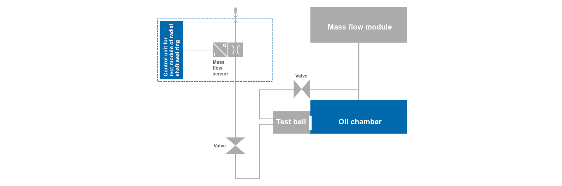
Special version: radial shaft seal test
Intelligent collaboration
The testing of a radial shaft seal on a completely assembled motor is carried out in collaboration between a mass flow module and a radial shaft seal module (RSS module). In the process, the mass flow module fills the oil chamber. The amount of air flowing out of the oil chamber through the radial shaft seal is gathered in a bell-shaped mechanical fixture (‘test bell’) and measured by the RSS module. This concludes the first test step. In the second test step, the mass flow module measures the entire oil chamber; for this purpose, the test bell is filled with the same pressure as the oil chamber through a changeover valve.